| C. Scott home | Back to projects page | MAS863 home |
"Make something visually interesting using an embedded processor."
For this assignment, I built a scrolling text display using a laser and a spinning polygonal mirror. Each facet of the 6-sided mirror traces out a different horizontal line from right to left; by sensing the mirror position and turning the laser on and off we can make 6 solid lines into lines of text. Click on the three pictures below for movies of the device in action.
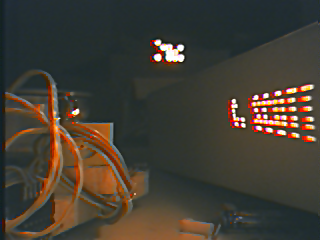
 This 1.1M AVI movie is the quickest download; it just shows some text
scrolling by. Use the binary clock in the background as a time
reference.
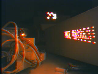
This 1.1M AVI movie is the quickest download; it just shows some text
scrolling by. Use the binary clock in the background as a time
reference.
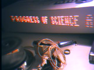 A 9.8M quicktime movie showing text from Article 1, Section 8, Clause 8 of the
U.S. Constitution -- the section on copyright. Note in particular the
reference to "for limited times" and the overriding purpose of
copyright legislation. The camera tracks around to give you a better
look at the actual device.
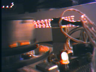
A 9.8M quicktime movie showing text from Article 1, Section 8, Clause 8 of the
U.S. Constitution -- the section on copyright. Note in particular the
reference to "for limited times" and the overriding purpose of
copyright legislation. The camera tracks around to give you a better
look at the actual device.
 This 5M AVI movie shows the turn on/turn off sequence for the scanner.
I flip the dip switch to start the motor spinning and you can see the
letters fall into place as the motor gets up to speed. We pan around
to show you the device, then I flip the switch to turn off the motor
and the letters gradually fall apart. In the final moments of the
spin-down you can make out the line-by-line scanning of the device.
This 5M AVI movie shows the turn on/turn off sequence for the scanner.
I flip the dip switch to start the motor spinning and you can see the
letters fall into place as the motor gets up to speed. We pan around
to show you the device, then I flip the switch to turn off the motor
and the letters gradually fall apart. In the final moments of the
spin-down you can make out the line-by-line scanning of the device.
OK, now that I've shown you what it does, how does it work and what does it look like?
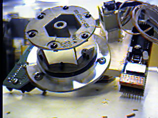
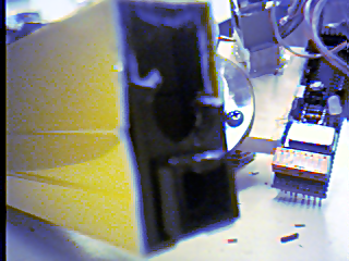
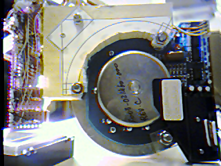
The picture above gives you a top view of the project. Notice the six-sided mirror assembly on the left. This mirror assembly is usually used in barcode scanners to let the laser scan several different possible locations for the barcode as it rotates. If you look at the top of the mirror assembly, you can see that the mirrors are not arranged in a perfect hexagon. On the bottom they actually are, but the mirrors are tilted in and out to give different vertical deflections. If you number the lines from 1 at the top to 6 at the bottom, the mirrors trace out 1, 4, 5, 6, 3, 2 as they rotate. I suspect the reason for the unusual ordering is to maintain symmetry in the mirror assembly so that it is not too out-of-balance as it rotates. I bought the mirror assembly used from Meredith Instruments ("The source for Laser Surplus"); you can find more information about it from their web site, assuming they've still got some left.
Just above and to the right of the mirror assembly is the laser mount, and at the far right you see the control electronics. The red switches at the bottom allow you to select one of sixteen different scrolling messages, as well as allowing you to turn on/off the control electronics and the mirror assembly motor.
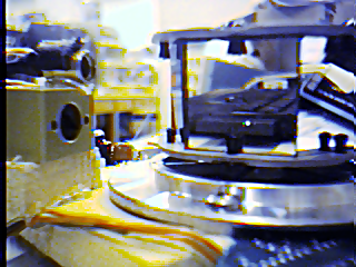
A view of the project from the side. The business end of the laser is on the far left. Note the gold colored block, which was a fancy $70 15mW 635nm laser diode (RLT6315G) from Roithner Lasertechnik until I burnt it out debugging the laser driver board. Now it is a very feeble red LED. Above it, with bits of black thermoplastic still clinging to it, is a 15-times-less-bright laser diode I hacked out of a laser level from Radio Shack. It's probably a 670nm laser with less than 5mW of power; a photopic response curve will reveal that the eye is about five times less sensitive to 670nm light as it is to 635nm light. Surprisingly, its driver module is simple enough that I can still modulate it at 56kHz, which is the approximate pixel clock rate of my text generator. (The mirror spins at around 3300 rpm; we divide a revolution into 1024 pixel times.)
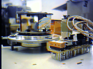
Another view of the project, with the yellow formerly-laser level from Radio Shack behind it. On the right you can see what used to be the business end of the laser level: it was surprisingly difficult to extract the laser from this thing, as all the bits were glued together. Nevertheless, I left the level-sans-laser still perfectly usable as an old-school plain-old level.
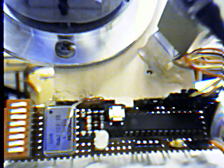
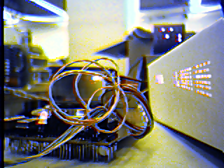
Above are two views of the electronics component of the project: it's just a simple PIC 16F876 microcontroller with one input from the spinning mirror's position sensor, and one output to control the laser power. Oh -- and four inputs from the DIP switches on the left to select the desired message, and one pushbutton to allow selecting a serial bootloader on power-up for reprogramming. The pushbutton also lets us calibrate the mirror --- its position sensor actually emits two pulses / four edges per rotation, but you don't know which edge corresponds to which position on the mirror: they are generated by some division logic on the mirror assembly's driver board with no consistent reset state. So pressing the pushbutton lets you cycle through the four possible alignments.
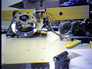
On the right above is a bottom view: you can see the stepper motor which spins the mirrors in the center as well as my funky wire-wrap job on the left. The laser and electronics are mounted to a piece of basswood screwed to the mirror assembly; you can download an XFig file for the paper template I used if you like (also an EPS version if that's better for you).
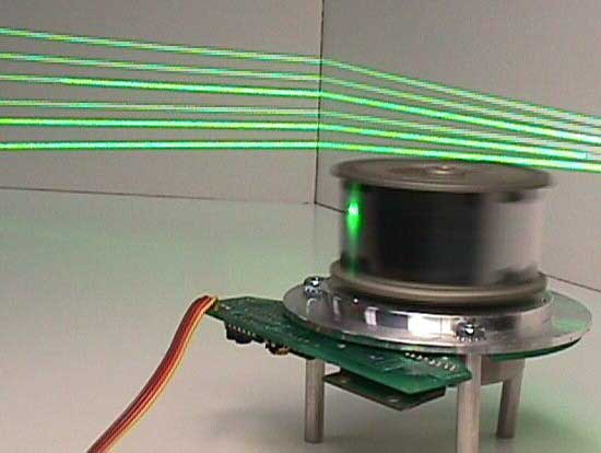
On the left is Meredith Instrument's catalog picture of the polygon scanner; on the right we show another view of our text generator in action to show the tricks we made this thing do.
Finally, for those interested in the software that makes this all work, here's the source code: laser.asm. This file depends on a 4x6(ish) font of the ASCII characters from 0 to 127 (although I've only included uppercase glyphs at the moment); you can look at this as a graphic or as the table (alphabet.asm) included from laser.asm. And the whole bundle of bits, with Makefiles and all, is rolled up into laser.tgz.

That's all, folks!
|
Copyright © 2002 C. Scott Ananian. Verbatim copying and distribution is permitted in any medium, provided this notice is preserved. |
cscott cscott.net cscott.net
|