| C. Scott home | Back to projects page | MAS863 home |
"Make something using the 2-d cutters out of as many materials as possible and which uses no fasteners."
This is a continuation of assignment one. This week, I actually made one of the spikes I designed last week. My apologies for the poor quality pictures: they were made with a $10 web cam. (That $10 web cam is destined for yet another project, but hasn't been cannibalized entirely quite yet...) I just think it's great that you can get *any* kind of picture into a computer from a device that costs $10.
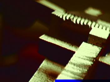
I used wood, aluminum, and two types of acrylic to make my spikes. The wood and acrylic were cut on the laser cutter, and the aluminum was cut on the water jet. The wood required multiple passes, and the laser jet driver doesn't compensate for spot width, so all the wood and acrylic parts came out slightly small. The aluminum wasn't well clamped down on the waterjet bed and ended up with a rough finish, making it slightly large. By mixing the too-small and too-large parts, I ended up with two "just right" spikes. Just proof that clever interlocking design can alleviate the need for precise tolerances!
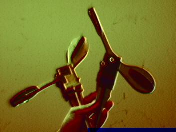
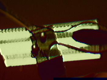
The part on the left above has wood uppers, metal and wood triangular spike bits, and acrylic "foot pedals"; the part on the right has tinted acrylic uppers uppers, wood "foot pedals", and again a mixed metal and wood spike. The wood uppers were made first and you can see a piece of black gaffer's tape on the left-hand part holding the axle in because the fit is too loose. I fixed the problem for the acrylic part on the right.
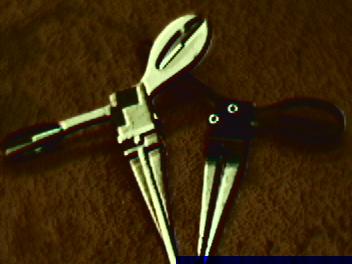
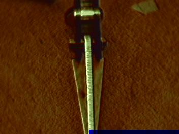
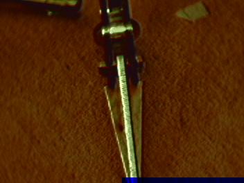
More gratuitous shots of the mostly-wood "taped-in axle" spike.
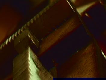
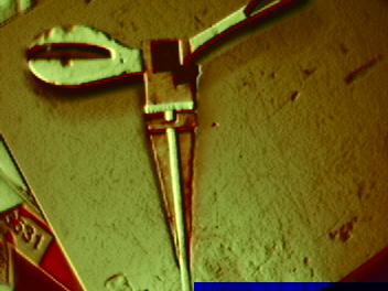
Above you can see the "jaggies" caused by improper clamping on the water jet. The part was vibrating back and forth as it was being cut, causing these serrated edges.
I'm claiming that the serrated spike edges are a feature, not a bug. The grooves help the spike stick in the ground better!
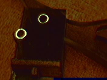
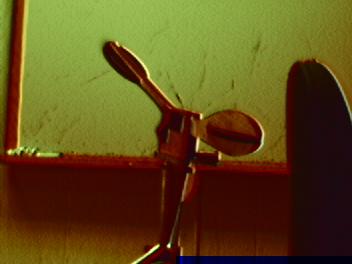
Ooh, look: acrylic is transparent. Held up to the light, you can see the details of the interior cam. The cam is actually positioned a little too high up in this picture, because when I shrank the axle hole diameter, CorelDraw decided to move the top-left corner of my circle as well.
In the other picture you can see the tight fit of the axle and cam-stop in the acrylic upper.
Not very far along into my cutting, I was stymied by two separate tool issues. First, that the laser cutter did not offer an adjustment for spot width, so I had to manually change all my dimensions to try and obtain a tight fit. Secondly, that OMAX Layout didn't like spline curves in the bezier file at all. And Corel seemed to have issues with properly flattening the curves into line segments.
So off I went to write software. Here's the preliminary result:

This program takes in Gerber or SVG files, optionally applies an
offset, and outputs an SVG or DXF file. For the DXF file, the curves
are approximated by elliptical arc segments, which OMAX seems to
support. It's not quite done yet, but parts of it are
getting there and the whole shouldn't be that far off. The whole
thing would have been much harder if not for the Batik SVG library and the
java.awt.geom classes in the Java standard library.
|
Copyright © 2002 C. Scott Ananian. Verbatim copying and distribution is permitted in any medium, provided this notice is preserved. |
cscott cscott.net cscott.net
|